|
|
|
Audio/Servo Driver Circuit by Scary Terry |
|
|
|
This is a circuit I've developed to drive a servo using a variety of audio sources. My goal in creating this was for a relatively simple, inexpensive and reliable circuit that doesn't require programming a microcontroller for each individual movement. I've used several of these circuits for more than eight years to provide mouth movements on Bucky skulls and other animatronic heads. They have been a very reliable addition to my haunt. As an audio source, I use MP3 players. For sounds that repeat, a cheap (often under $10) MP3 player from a surplus dealer works well. For sounds that I need to control more precisely, I'll use an MP3 player that can be controlled either directly or with a microcontroller like this one from SparkFun.Here's a web page I've put together showing how-to install a servo in a Bucky skull. As long as there is sound present, the servo will drive to its "max" position. If the sound is short in duration, the servo will not have time to drive to "max" but will drive part way and return to "min" position. While this method of moving a mouth is not perfect, it's pretty good and I'm very happy with the effect. It's important to remember that any sound will drive the servo, voice, music or noise, so if you're trying to make a Bucky mouth move to a voice track, you shouldn't have music in the background of that particular track. There are several ways to include music or other sounds and still have the appropriate jaw movement, one is to split the stereo tracks with only the voice on one (this one would feed the driver circuit) and the music or sound effects on the other. Jeff Stevens came up with a solution and I include his email at the bottom of this page.
|
|
|
|
First of all, if you want to do it the easy
way....... |
|
Cowlacious Designs offers this circuit completely assembled. Believe me, this is a much easier way to build this circuit than trying to do it from scratch and it offers some features the original design does not have. (Note: I am not affiliated with Cowlacious Designs. I have given them permission to use my design but I make no money from the sale of the product. Please contact them if you have questions about their products). |
|
|
|
|
|
|
|
|
|
|
|
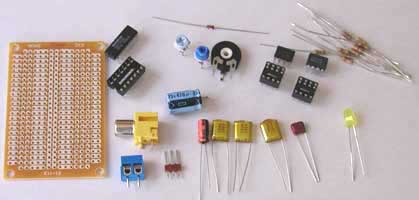
Parts List |
|
|
|
|
|
|
|
|
|
|
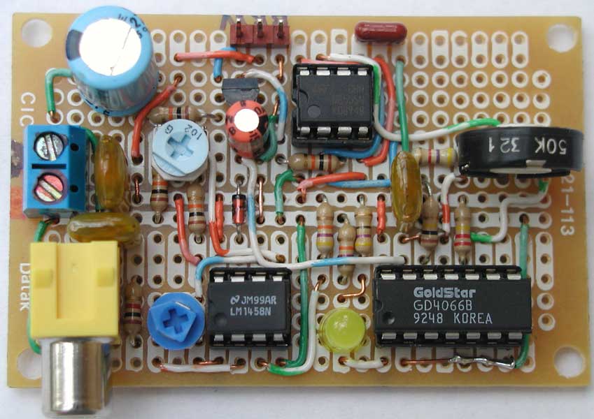
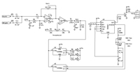
Circuit Description From the output of your audio source, the center conductor goes to "Audio In", the outer shield goes to ground. The signal is amplified by U1a whose gain is controlled by R3. You should be able to use audio sources from a line level to a "reasonable" speaker level source and adjust the gain using R3. U1b compares the audio from U1a to a reference voltage set by R6 and sends a switched output voltage through diode D1 to CMOS switch, U2. R6 should be adjusted so that with no signal, LED D2 just turns off. Once a signal is present, R6 can be used to fine tune the servo action. Capacitor C2 is used to smooth the servo operation. I show a 10uf capacitor but have used values as low as 2.2uf depending on need. Lower values (or no capacitor at all) make things jerky, higher values slow down the servo action. I recommend experimenting to find out what's best for your situation. You may want to consider just putting in a 0.1" spacing socket in place of C2 so it will be easy to substitute different value capacitors. The Cowlacious boards actually have three capacitors installed and a jumper to select which one you want to use. U2 is simply used as a switch. In this case, a high on pin 12 closes a switch between pins 10 and 11, triggering the servo driver (actually, it's not a full closure but about 90 ohms of resistance). A high on pin 13 closes the switch between pins 1 and 2, which is what lights the LED. (The LED is optional, but it really makes it easier to make adjustments and insure the circuit is working correctly. If the LED is not used, pin 13 should go to ground). There are two additional switches that may be used in this IC, pin 5 controls the switch between pins 3 and 4, and pin 6 controls the switch between pins 8 and 9. This is great for adding a pair of LED "eyes" that flash to the sounds. The circuitry surrounding U3 is the servo driver. In its original form, the circuit was a "servo tester". I've made some modifications to make it suitable for this application. Variable resistor R10 sets the starting point of the servo, so at one extreme, the servo will start at 0 % and go all the way to 100% while at the other extreme, the servo will start at 99% and go to 100% of its travel. Capacitor C5 helps to keep the power supply stable during servo operation. J1 is the connector for the servo. This circuit, without a servo attached, only draws about 2 ma, but actively driving a servo, draws around 600 ma. I'd recommend a 5 volt power supply of at least 1 amp. I've found good sources for this type of supply to be MPJA and All Electronics. My favorite place to purchase servos is ServoCity. They've got good prices and I've never had any problems with their service. My current favorite standard servo is the Hitec HS-425BB. With dual ball bearings and nylon gears, it's a good compromise between performance and price. I've had a report of one guy driving seven servos off the one circuit and it worked fine. The important thing to keep in mind when driving multiple servos is that you need a power supply that will handle the combined current of the servos.
|
|
|
|
As I mentioned at the beginning, the servo will respond to
any sounds it's given, so if you have a voice track with music in the
background, the servo will not only respond to the voice but the music as
well. Jeff Stevens had a way to solve this problem and here is his email to
me..... |
|
|
|
Dear Scary-Terry, I am writing you about a new method for
using your audio-servo driver. Here’s
how you do it. First, you record your sounds on a two channel cd and player.
On one of the channels have the voice and all other audio effects that you
want people to hear, such as music or thunder etc. On the other channel, whether
it is the left or right it doesn’t
matter, you record the sounds that you want to drive the audio-servo driver.
You connect this channel to the audio driver. You then use a y-splitter to
take the first channel, the one you want people to hear, and connect it to
both channels on the amplifier or amplified speakers. You now have the
ability to have music without it activating the skull. The effect sounds
stereo because it is coming out of two speakers, but both are playing the
same thing. That is the only disadvantage. Let me know what you think. -Jeff
Stevens |
|