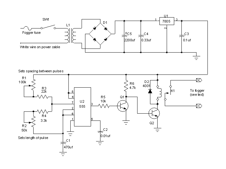
Here's the fogger timer circuit using the 555 timer. This circuit works very well except for the fact that the pulse and spacing times are not completely independent of each other as shown by the table below.

   
  Click here for a pdf version.  

 
  This chart shows the relative position of the knobs (R1, R2) with respect to timing for the "555" circuit. "Min" is full counterclockwise, "Max" if full clockwise. "On Time" is the time the fogger is triggered. "Spacing time" is the time between fog pulses. Times are approximate and are dependent on components used. As you can see from the chart, "on time" tracks very consistently with the position of R2. "Spacing time" is dependent on both R1 and R2.  
  Pulse length (R2) Spacing length (R1) On time Spacing time  
Min
Min
1 sec 8 sec
Mid
Min
5 sec 12 sec
Max
Min
15 sec 22 sec
Min
Mid
1 sec 14 sec
Mid
Mid
5 sec 17 sec
Max
Mid
15 sec 29 sec
Min
Max
1 sec 36 sec
Mid
Max
5 sec 41 sec
Max
Max
15 sec 53 sec


  Parts List  
 
SW1 SPST toggle switch
L1 Small 120/12 volt transformer
D1 1A diode bridge
D2 1N4001
C1 470 uf 16 volt capacitor
C2 0.01uf 50 volt capacitor
C3 0.1u 50 volt capacitor
C4 0.33uf 50 volt capacitor
C5 2200uf 25 volt capacitor
U1 7805 voltage requlator
U2 555 timer
R1 100k linear taper pot
R2 50k linear taper pot
R3 22k 1/4 watt resistor
R4 3.3k 1/4 watt resistor
R5 10k 1/4 watt resistor
R6 4.7k 1/4 watt resistor
K1 5v relay with 1amp spst contacts
Q1, Q2 NPN transistor 2N2222
 

  Halloween Home last update 5/2004