|
|
Skelevision by Scary Terry |
|
|
|
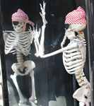
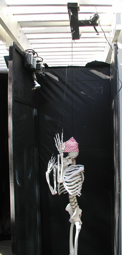
This is a prop I call Skelevision and it was used for the first time Halloween 2005. Like any new prop, you're not sure how the Trick-o-treaters are going to react until you try it out. Well, I've got to say that Skelevision was a definite success. It scared many while others were in awe. It rarely failed to get a reaction. |
|
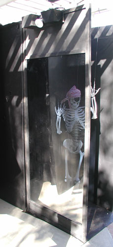
A note about the pictures....This prop requires total
darkness for the effect to work. It also involves mirrored surfaces. Neither
one of these features make it conducive for taking pictures. The pictures you
see here were taken after some of the enclosure was removed. You can click on
any of them for a larger image. |
|
|
New 7/2006 |
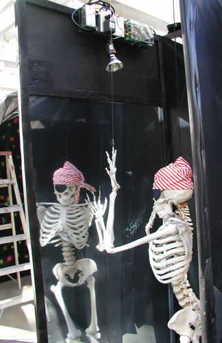
This last February, we had a CalHauntS meeting
at my house and I set up the Skelevision for
everyone to see. They all seemed to like it, but the comment I got more
than once was that the skeleton needed to move toward the trick-or-treater.
Not being one to shy away from a challenge, I decided to do this. The
skeleton now travels about 6' forward on an overhead track. I've included
some pictures and a description of how I made this mechanism and here's
a video of the testing phase of this project. |
|
|
|
|
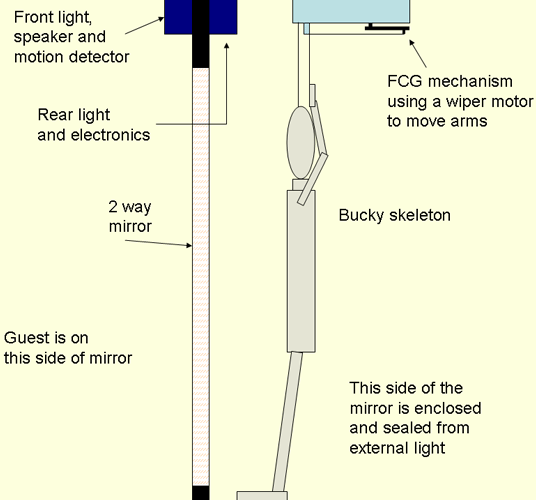
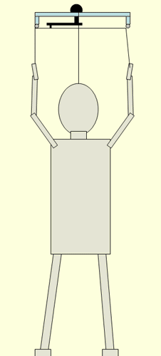
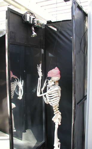
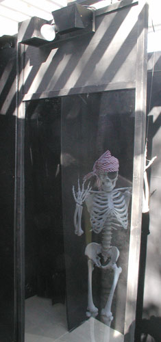
The drawing to the right shows the basic components of Skelevision. It consists of a 2-way mirror, a Bucky skeleton attached to a Flying Crank Ghost (FCG) mechanism, a motion detector, a couple of lights, a speaker/amplifier and a circuit controlled by a Basic Stamp. It now also includes an overhead track (not shown in the drawing) which allows the Bucky to travel about 6' forward and back. In my haunt, it was part of a maze. The guest would enter a hallway and see themselves in a mirror at the end of the hall. All of a sudden, the lights would go out, spooky sound effects would play and then a skeleton would appear where they previously saw themselves in the mirror. The skeleton would be frantically waving its arms. After a few seconds, the skeleton would disappear and the guest would once again see themselves in the mirror. The setup is fairly straight forward. The 2-way mirror is made from a 3'x6' piece of clear acrylic ($30 from Lowe's) covered with a layer of Gila " Privacy Mirror" film ($25 a roll at Lowe's). It's mounted in an 8' tall wooden frame with thin pieces of plywood to fill in above and below the mirror. |
|
|
|
|
|
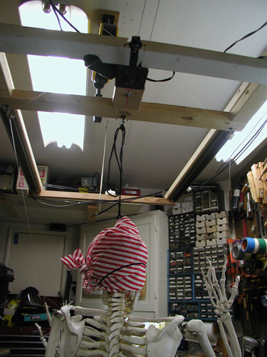
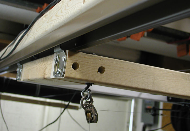
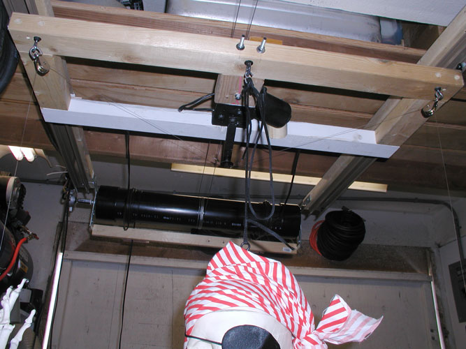
The overhead track mechanism consists of a pair of 8 foot
long "wardrobe door" tracks (purchased at my local home center for
about $15 each) mounted to a wooden frame. The Bucky skeleton/wiper motor
mechanism is attached to a trolly that rides along
these tracks. |
|
|
|
|
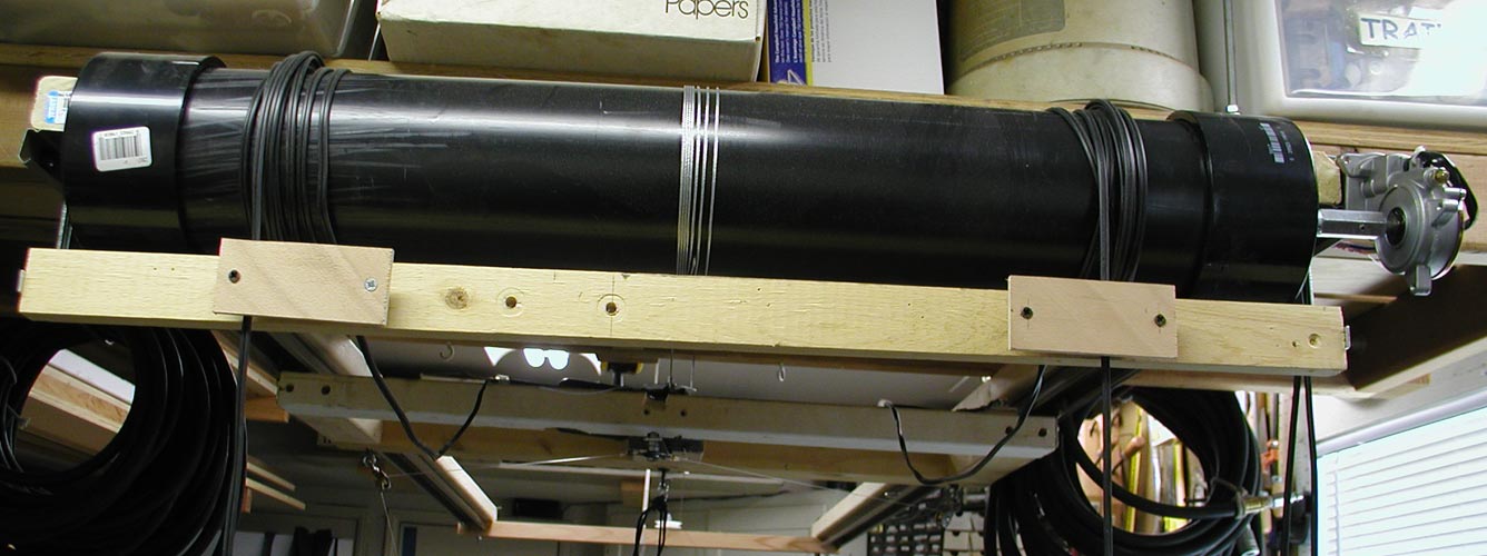
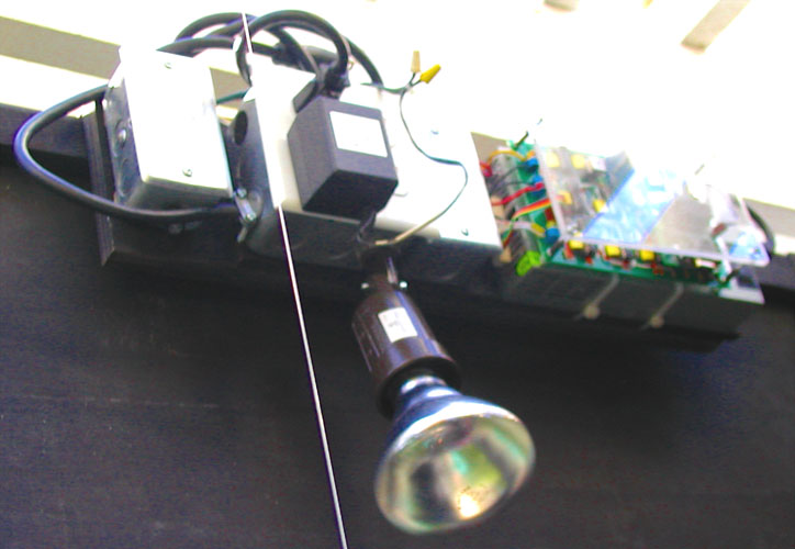
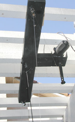
The drive mechanism for the trolly
consists of a piece of 4"ABS which rotates around bolts mounted in the
two ABS endcaps (see below for pictures). The trolly is connected to one end of a piece of 1/16"
stainless steel cable, which then goes to a pulley at the far end of the
track, loops around, comes back to the drum, winds around several turns and
goes back to the trolly. When the drum is rotated
in one direction, the trolly goes forward and when
rotated in the opposite direction, it goes backward. |
|
|
|
|
|
|
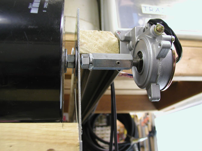
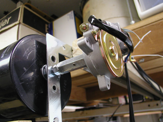
The ABS drum is driven by a 12 volt automotive motor and speed controlled by a Parallax HB-25 motor controller. In the above picture, there are two wires on the drum on either side of the steel cable. One provides power to the wiper motor (for moving the Bucky arms), the other connects to a track switch detailed below. |
|
|
|
|
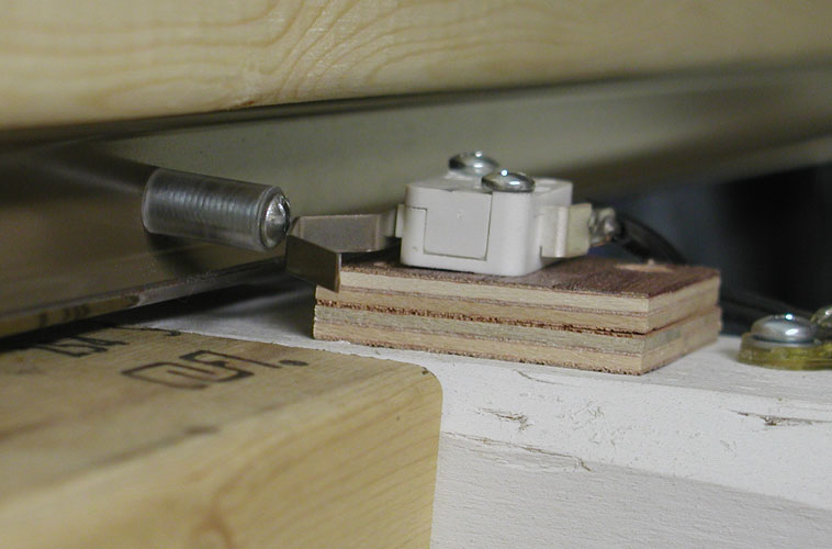
Attached to the trolly is a microswitch (right) which tells the Basic Stamp
microcontroller where the trolly is. Along the
track, I've placed screws/spacers to trip the switch. Right now, I'm just
using two points, one for the forward direction and one for reverse to tell
the Stamp when to start slowing the trolly. |
|
|
|
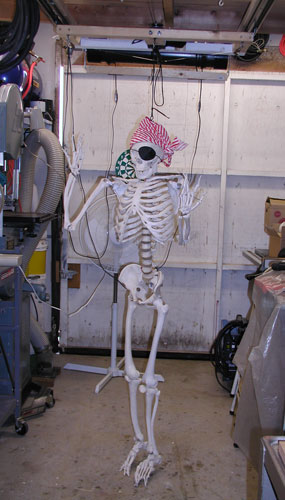
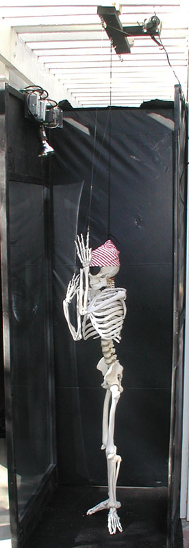
The Bucky skeleton is attached to an overhead mechanism similar to the Dancing Skeletons rig. The main difference between the two mechanisms is that the center line on the Skelevision does not move, it's attached using a static line between the mounting ring on top of the Bucky and the overhead support. The arms are attached to the rotating mechanism using fishing line or other invisible thin line through pulleys on the overhead support. Like the Dancing Skeletons, the Skelevision is powered by a wiper motor, but in this case, the motor is fed with a full 12 volts using the high speed terminals on the motor. I found the quick arm action to be the most effective. Because of the extra stress of the moving arms, I had to reinforce the Bucky arm attach points by drilling through the existing screw holes and attaching the arms with long #10 screws and nuts.
|
|
|
|
|
|
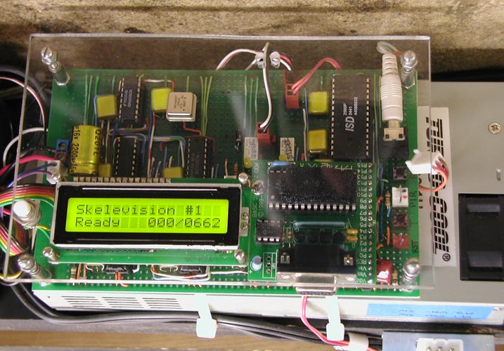
The Electronics |
|
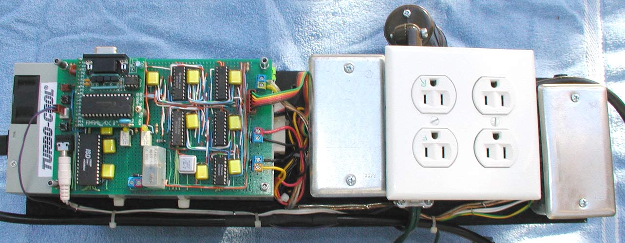
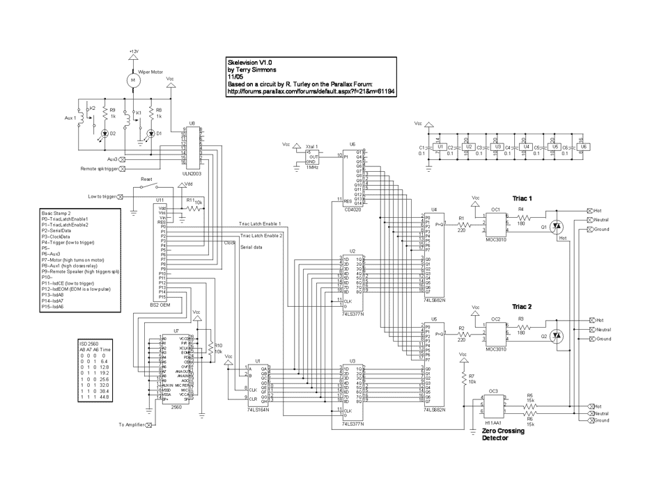
The electronics for Skelevision are based around a light dimming circuit that R. Turley posted to the Parallax Forums in Jan. 2005. I've modified the circuit as a fixed two channel dimmer and added a ChipCorder for sound effects and also relays for control of the wiper motor and external sound effects. The circuit is controlled by a Basic Stamp II. I've also added a display just because I've never done that before. All 120 volt components are physically isolated in an enclosed electrical box for safety (see photo below). Click here for a .png image of the schematic or for a full sized .pdf of the schematic. Also, here's a parts list. See below for ideas on a simpler way to do this. |
|
|
|
|
|
|
|
|
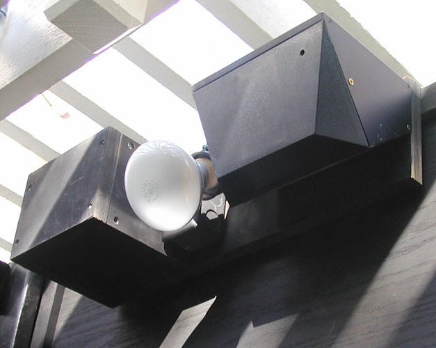
All the electronics are mounted in a "saddle"
that fits over the top of the mirror frame. To the left is the front part
which consists of the speaker, front light and motion detector. To the right is the back side and the bulk of the electronics. |
|
|
|
Simpler
Electronics |
The dimming circuit I used, while not overly complicated, is not an easy build on a "breadboard" and is definitely not a beginners project. Here are some thoughts on how to simplify the electronics:
|
|
|
More
Pictures |
|
|
|
|
|
last update 12/2016 |