|
Incorporating a Digital Sound Recorder into your Halloween Projects continued................. |
|
Now it's time to get into the circuits and make another decision or two. Obviously, you need some way to record onto the ChipCorder and some way to playback. In the following three circuits, I'm presenting you with the option of:
My preference is for the separate recorder board and independent playback boards. I keep the recorder board by my computer and when I need to record a chip, I just pop it out of the playback board, into the recorder board, do the recording, then back into the playback board. I use several ChipCorders in my Halloween projects and this is the best setup for me. |
|
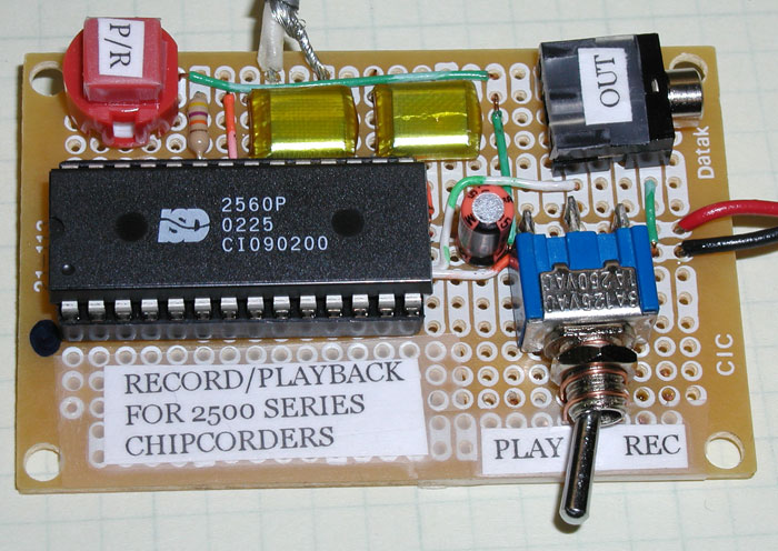
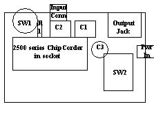
So here are the three circuits. The first is the recording (or recording/playback). Next is the switched playback (starts to play when switch is closed, continues to play whether switch is open or closed until message ends) and finally the looped playback (plays the message over and over forever). If you haven't done much electronic work in the past, please don't be intimidated by the fact that the ChipCorder has 28 pins. Take a closer look. On the most complicated circuit, the one for recording, of the 28 pins, 8 are not connected at all, 14 go to the negative side of the battery (ground) and two to the positive side of the battery. That leaves just four pins to worry about, an input, an output, the play/record selector and the pin that starts the play/record process. For power in all circuits, I show a 4.5 to 5.5 volt power source. This can be three AA (or C or D) batteries in series (head to tail) in a battery holder, a 5 volt regulated wall wart or whichever way you want to come up with around 5 volts. Click Here for a more advanced version of the ChipCorder recorder that will allow you to address memory locations. |
 |
|
 |
 |
|
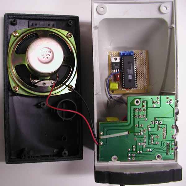
This
is an example of the "looped" circuit built into an inexpensive
computer speaker. I've added a 5 volt regulator (7805) so
the ChipCorder will run off the speaker's 12 volt power supply. Schematic
is at right.
|
 |
 |
| Here's a parts list. The ISD 2500 series of ChipCorders has been discontinued but as of 8/07, they're still available from Jameco. I list DigiKey for the other parts mainly because the Jameco website is so difficult to use for looking up part parts without a specific part number. I list the Radio Shack circuit boards because I like them. You probably have some hook up wire, it doesn't take much, but just in case, I've listed that. The last three columns address which board the various parts are used in. |
|
| On to page 3 |
| Halloween Home | last update 8/2007 |